MHB Client - CPMS – Principal Contractor
Ultimate Client – Network Rail
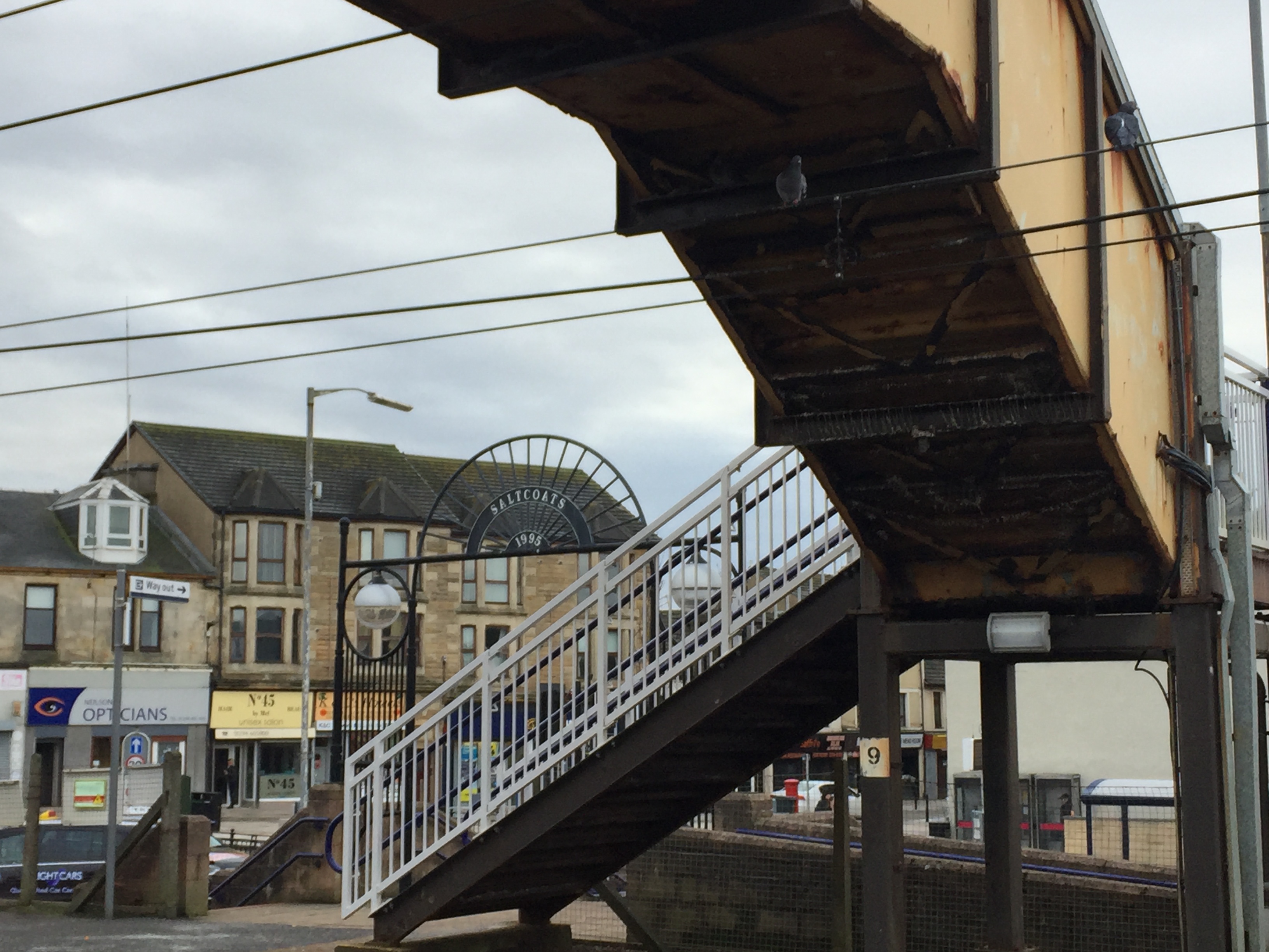
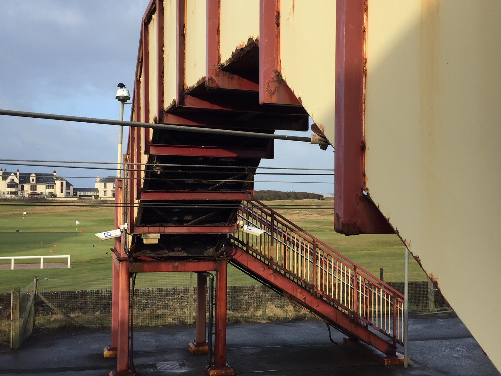
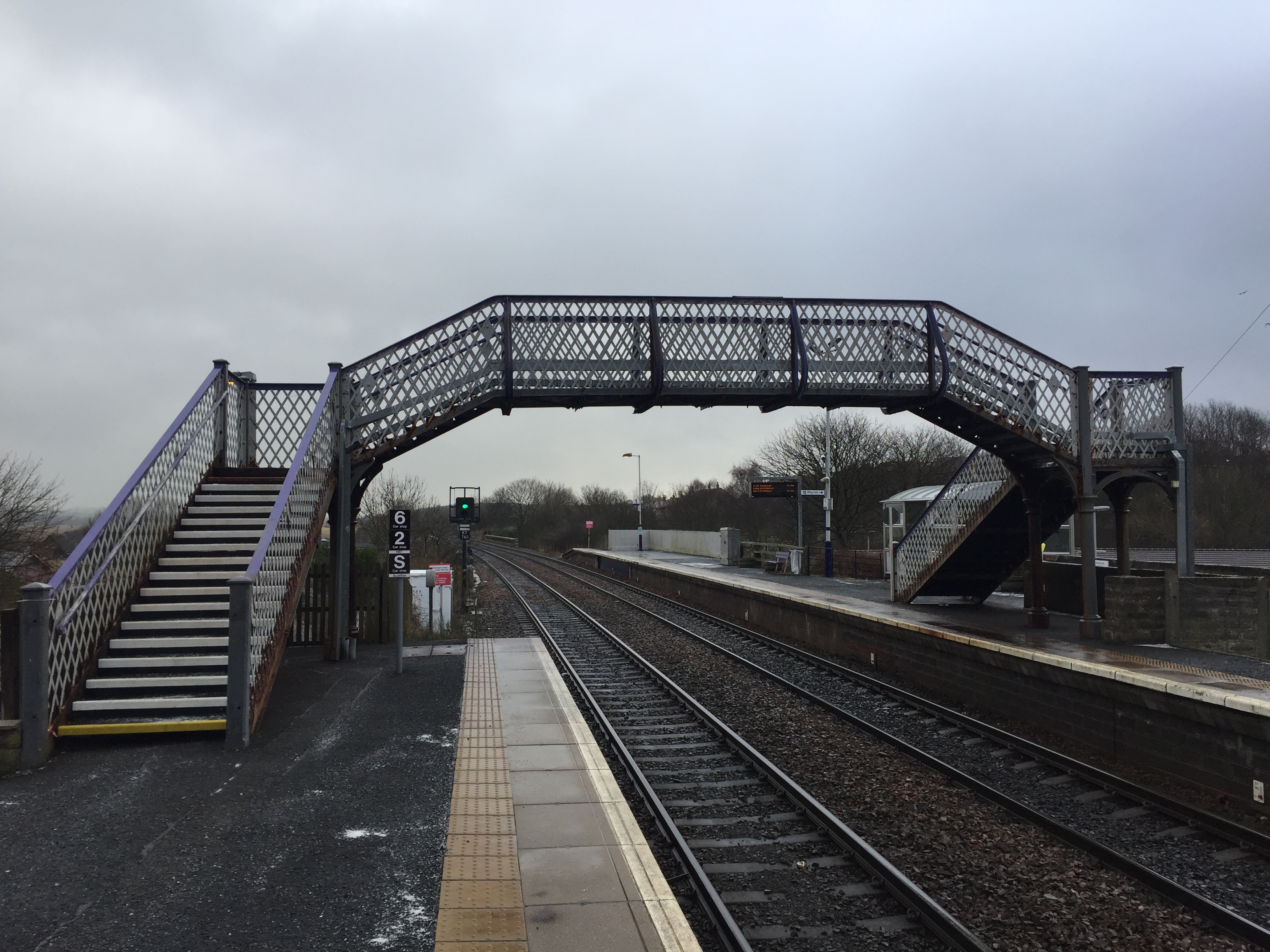
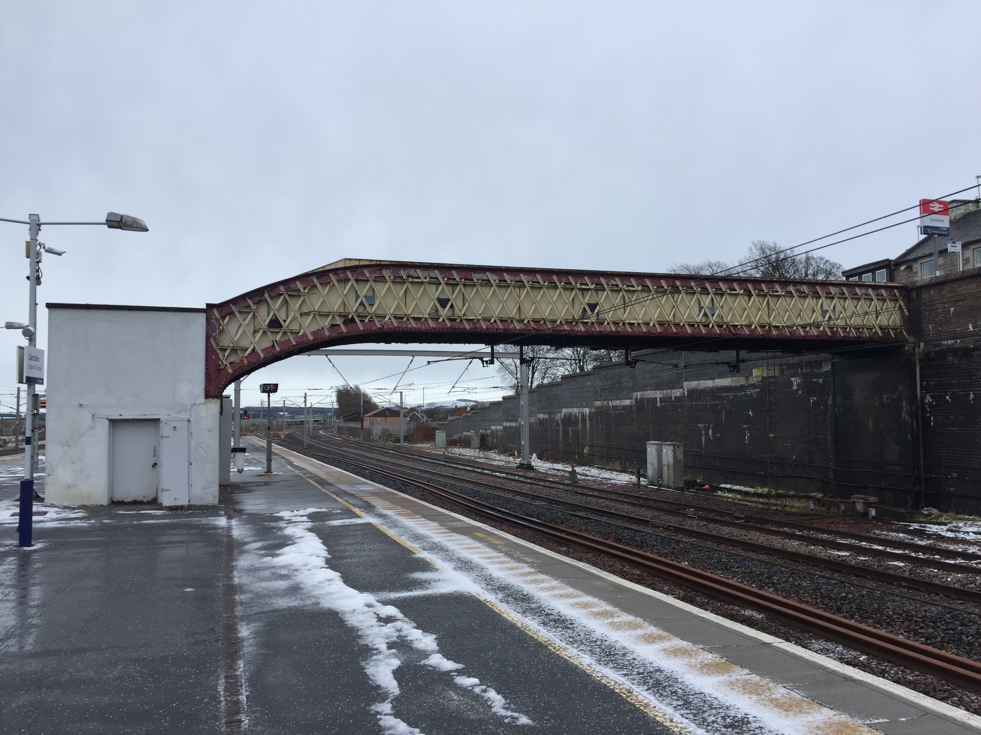
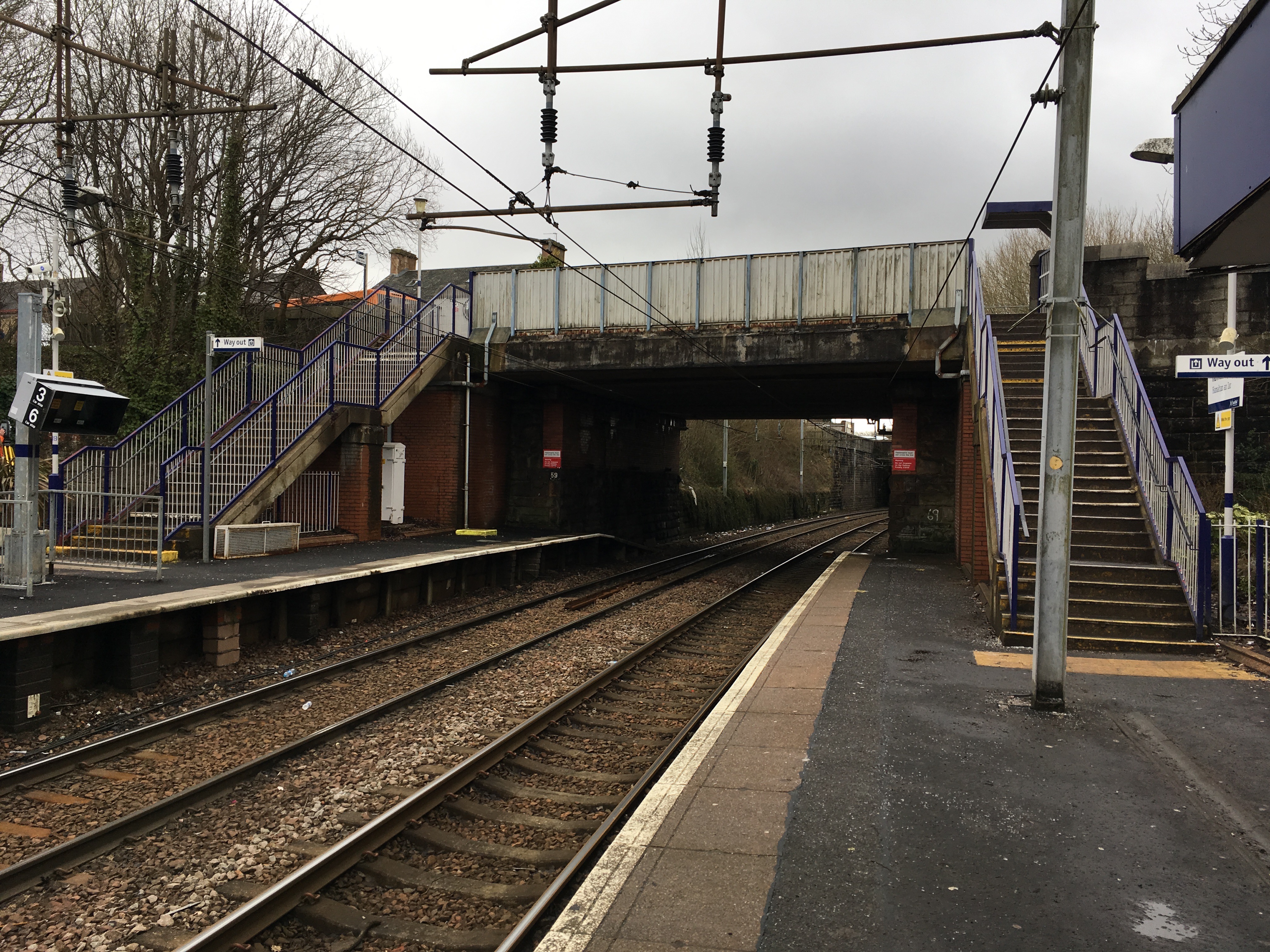
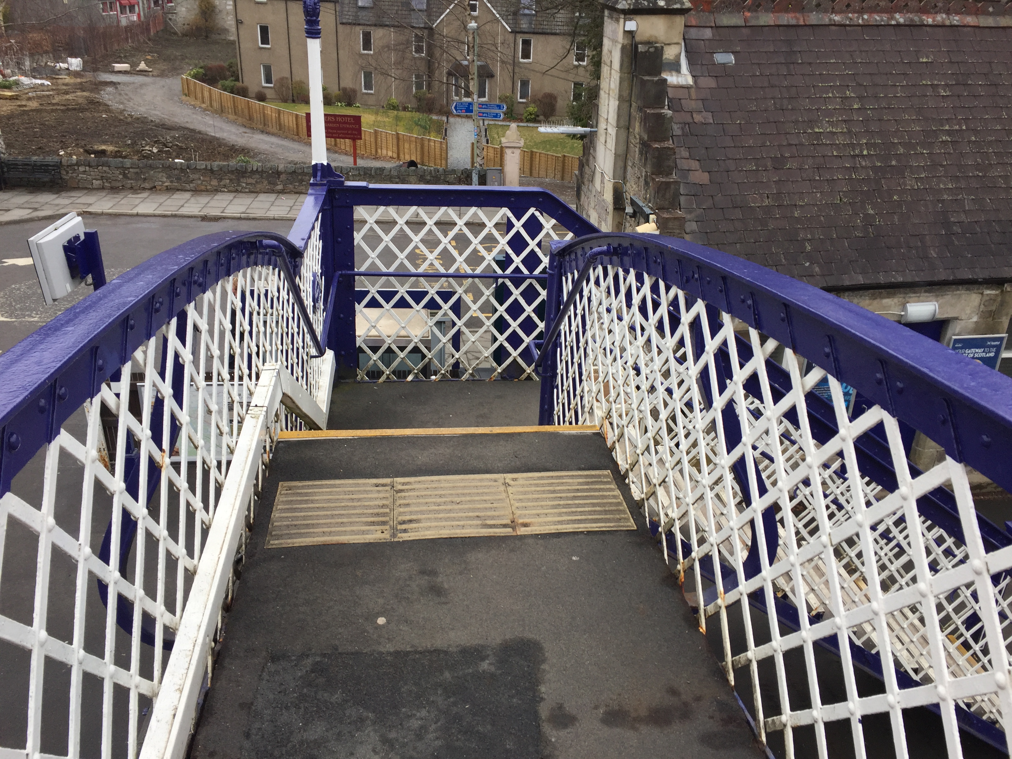
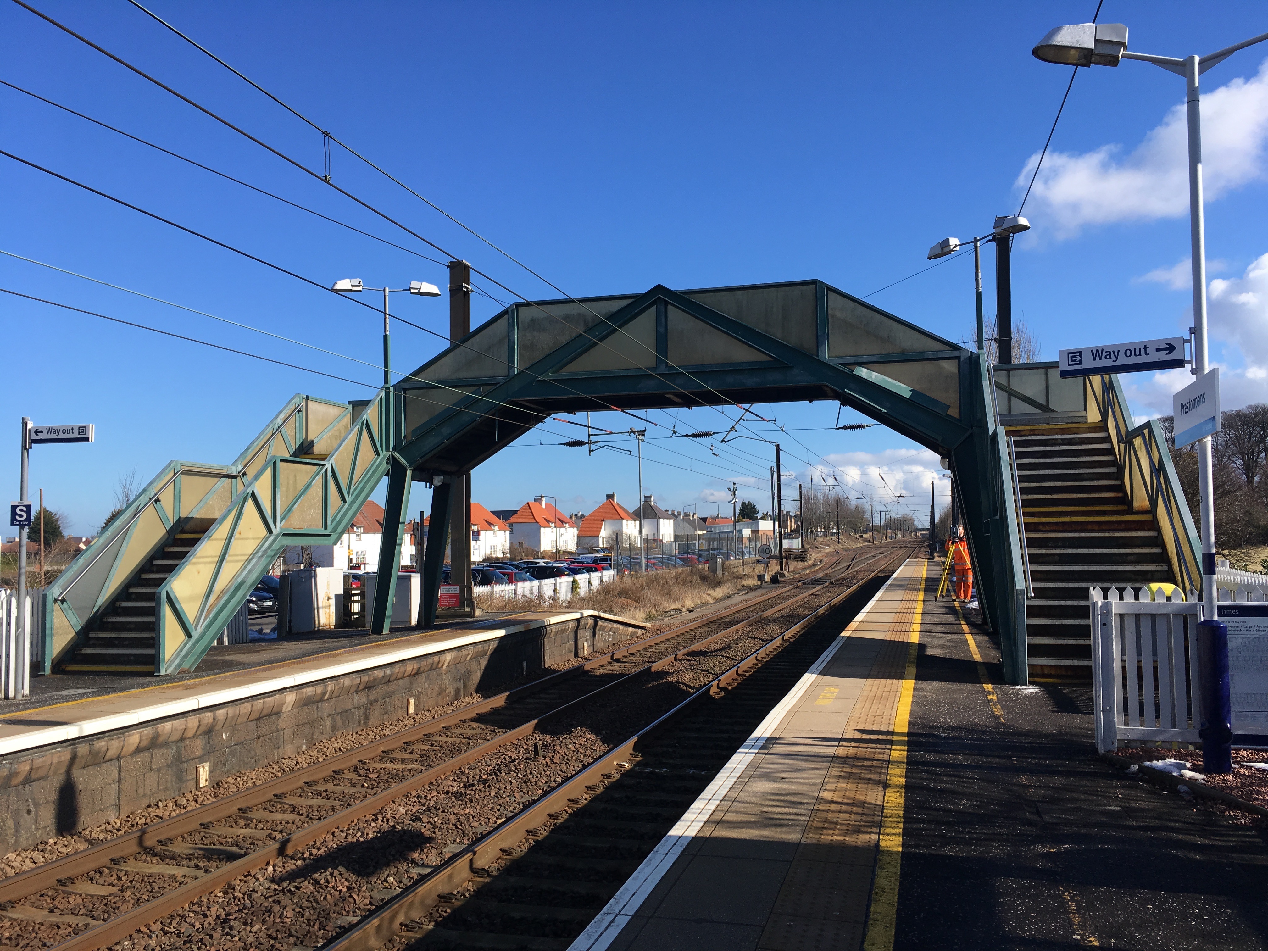
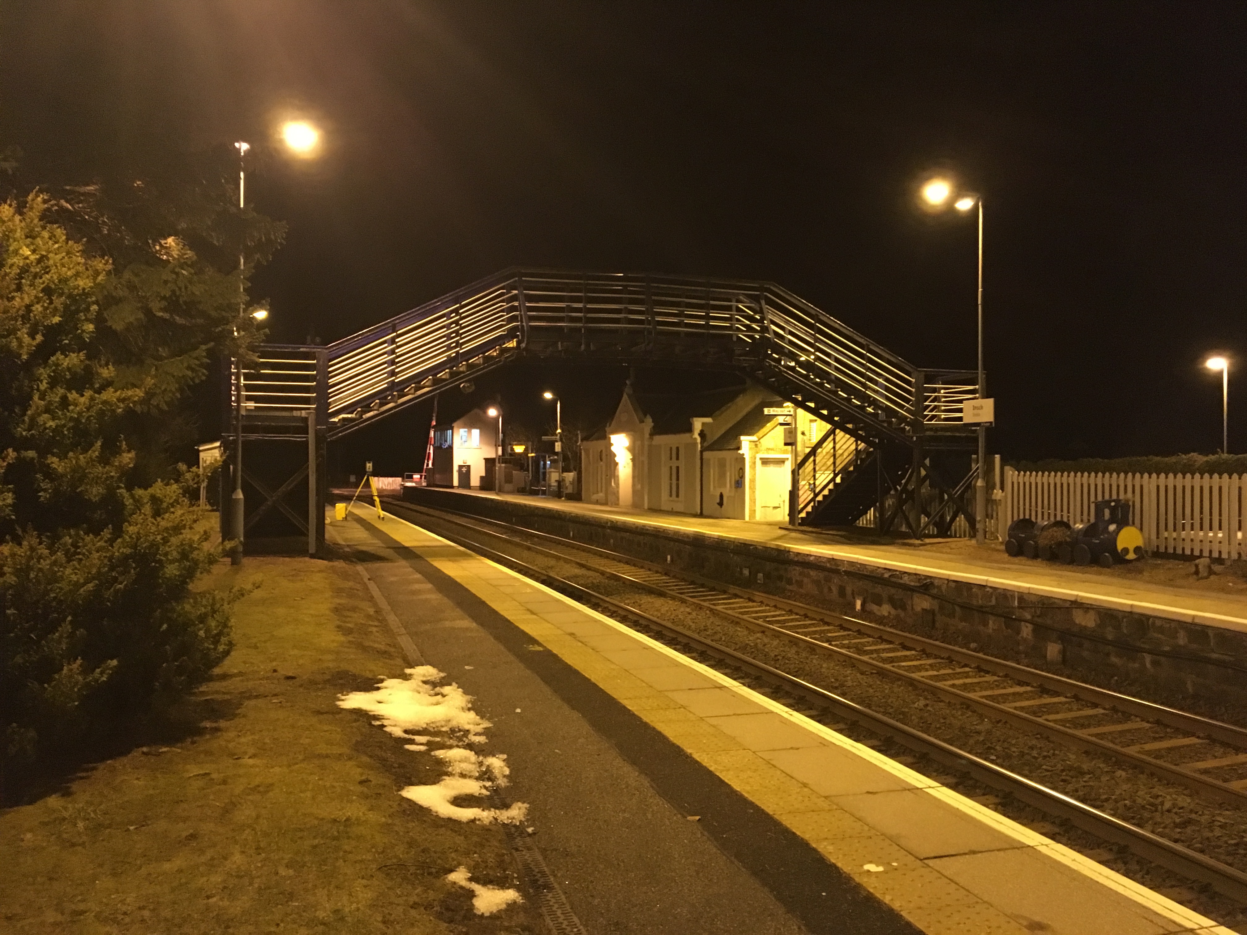
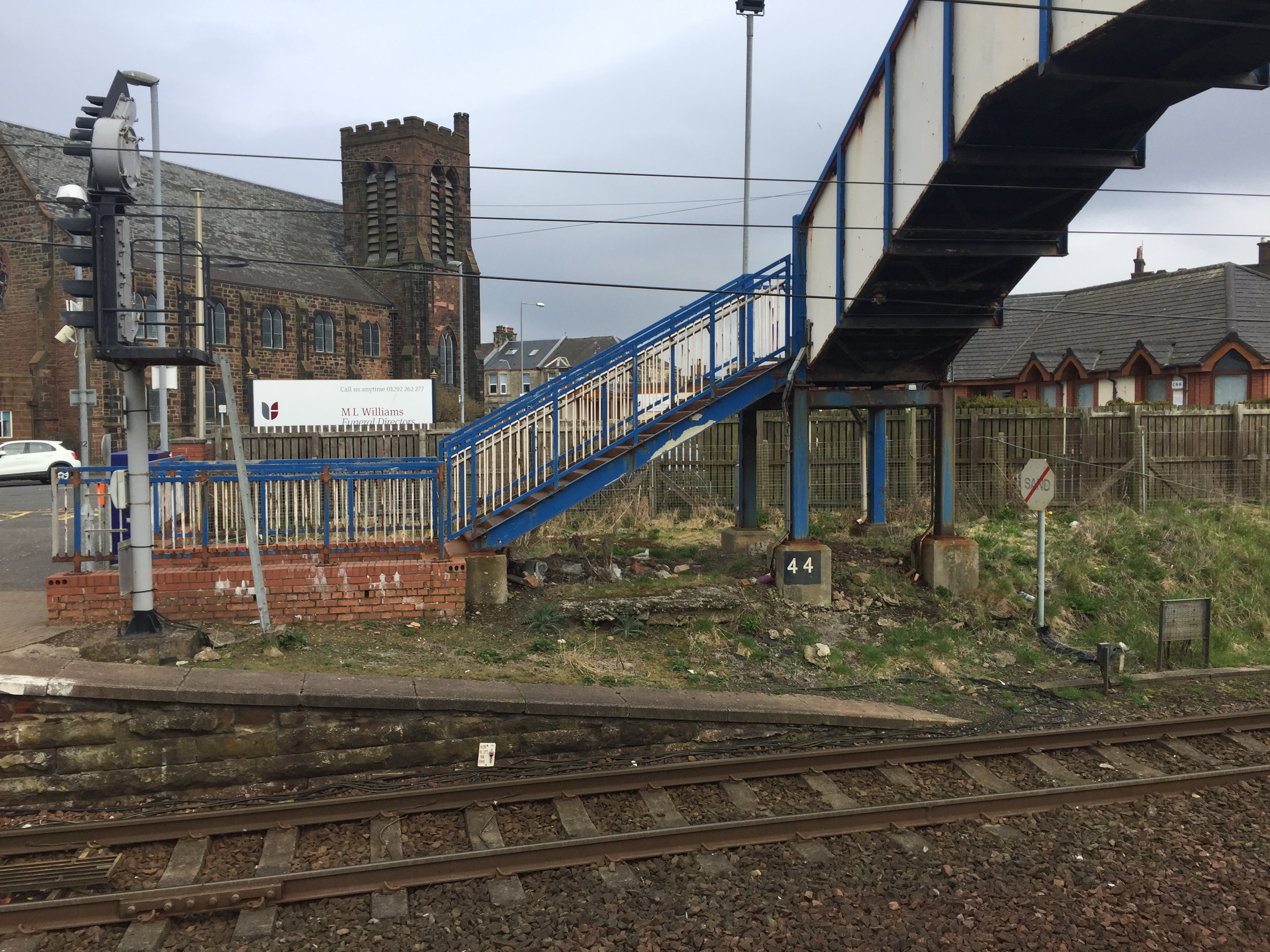
On behalf of CPMS, MHB undertook Topo Surveys of 12 no. station footbridges to support structural and condition assessments. The drawings were delivered in 3D AutoCAD.dwg format.
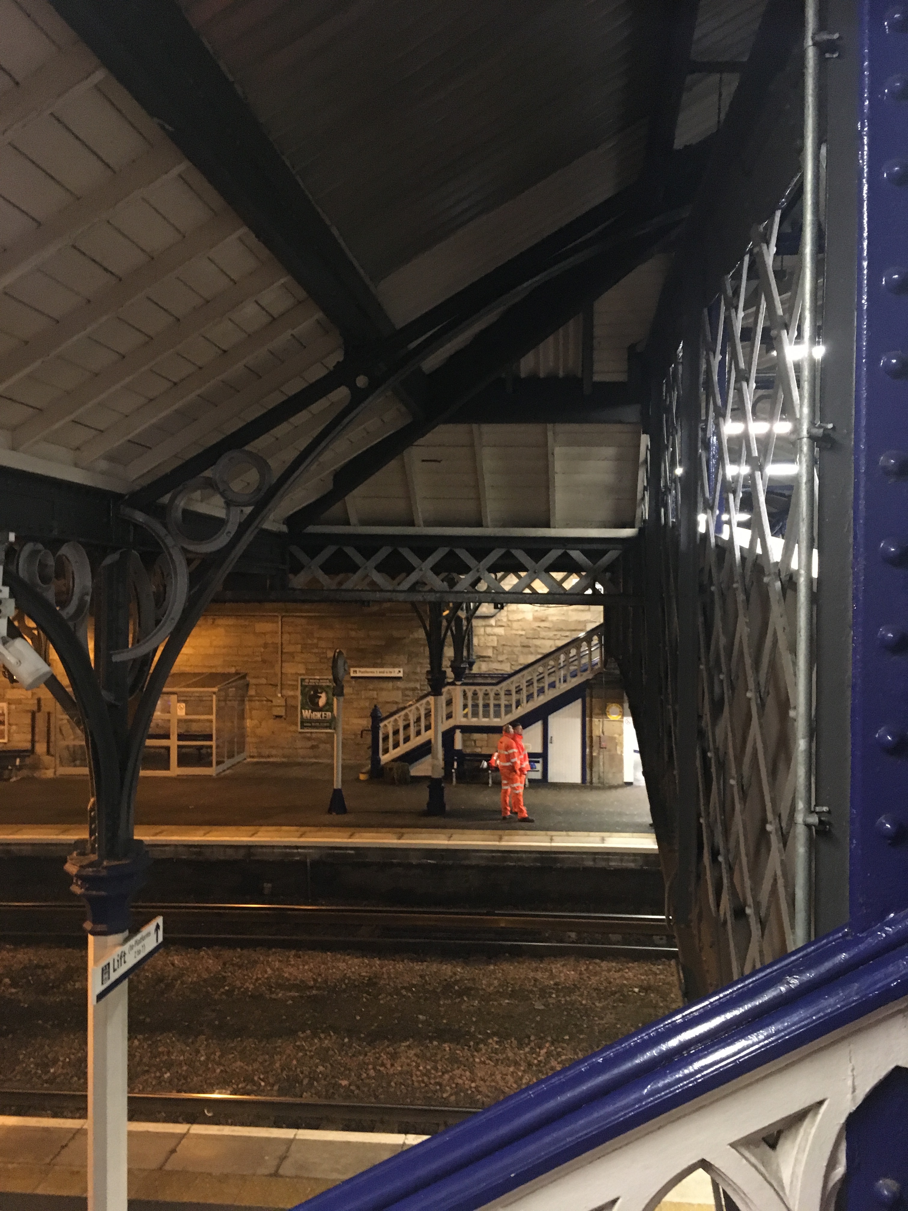
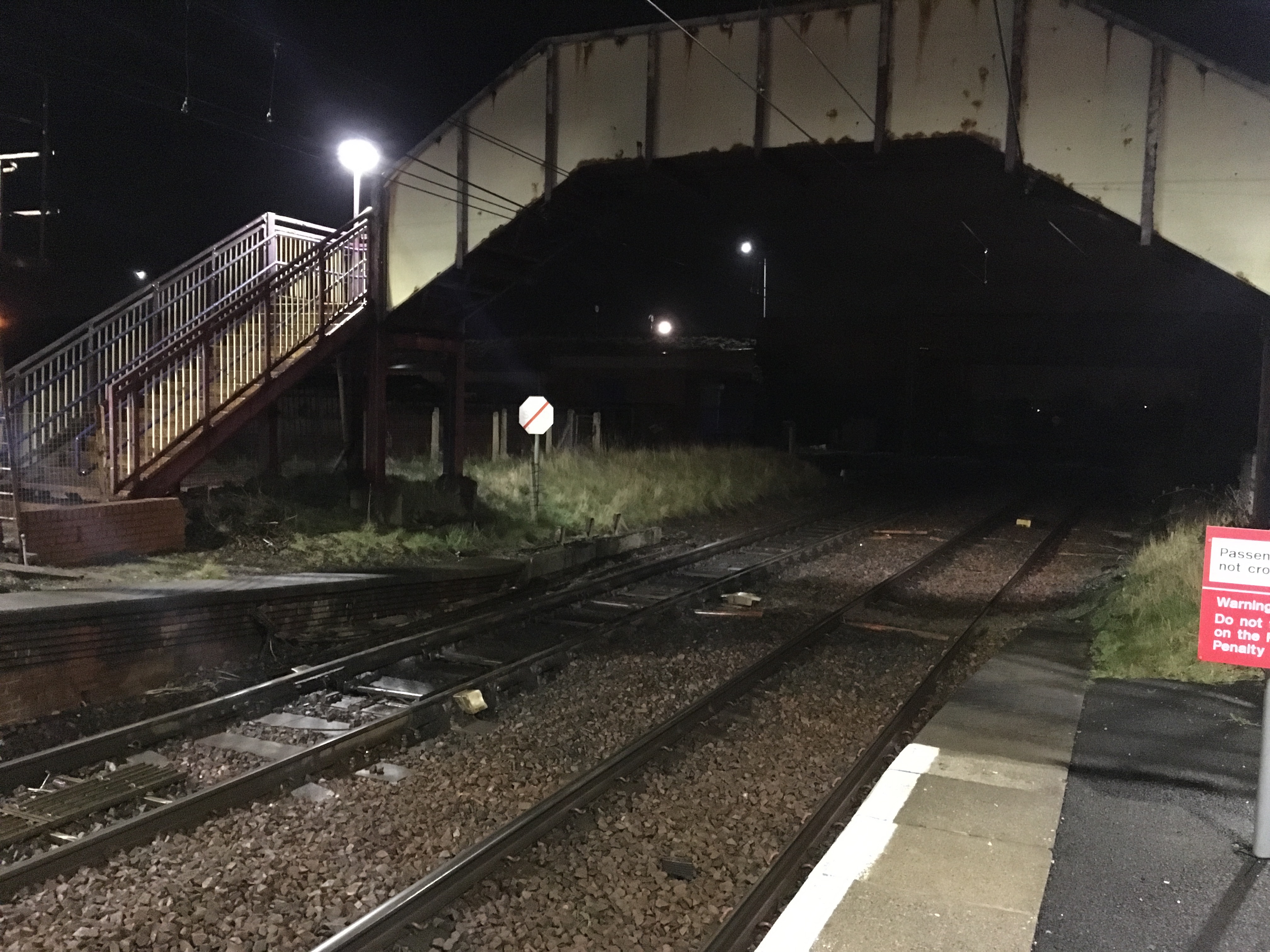
The topo survey of the footbridges required a mix of working during daytime in normal high street conditions and at night under track possession (times when there are no train movements). The client CPMS arranged possession times with Network Rail and provided a schedule from which MHB could plan additional day shift visits to allow efficient completion of the onsite survey works. Tracks, platform edges, track furniture and sections of the footbridge not accessible form the platform were surveyed under possession. During normal operating train times when survey work was being carried out no equipment was placed within 1.25m of the platform edge in accordance with Network Rail PTS.
The key challenge of the footbridge surveys was the intricacies of the structure and the requirement of multiple total station set ups to capture all aspects of the bridge. The works were undertaken using a Trimble S8 High Precision 1” total station. Angular Accuracy is accurate to 1” (0.0003°) with electronic distance measurement accurate to ± 1mm + 1ppm in prism mode and ± 3mm +2ppm in direct reading (reflector-less) mode. This is above the minimum standards for total station accuracy as outlined in section 5.9 of Network Rail Document NR_L3_TRK_3101 which states a minimum angular accuracy of ±2” and EDM accuracy of ±2 mm + 2 ppm. All observations on rails were taken with prism on a rail foot adaptor to get the inside running line which is 14mm below the head of the rail.
Before commencement on each site a reconnaissance was carried out to plan the optimum total station locations. These were positioned in areas which allowed large sections of the survey to be completed to minimise total number of set ups required, and thus possible introduction of error. Lines of sight were taken into consideration as well as safety of location and ensuring not to block or hinder public access during station operational hours.
The total station was set up over a survey nail and levelled to gravity. The instrument was levelled using electronic bubble until 3” or below in both pitch and roll was indicated. The compensator was switched on in case of any minor vibration from passing trains etc. All required survey control was set in from the initial set up. A base line longer than the extents of the site was selected from which GPS coordinates were observed using Trimble R6 dual frequency GNSS receiver with choke ring antenna. The completed survey could then be transformed to OS National Grid coordinates in Trimble Business Centre post-processing software.
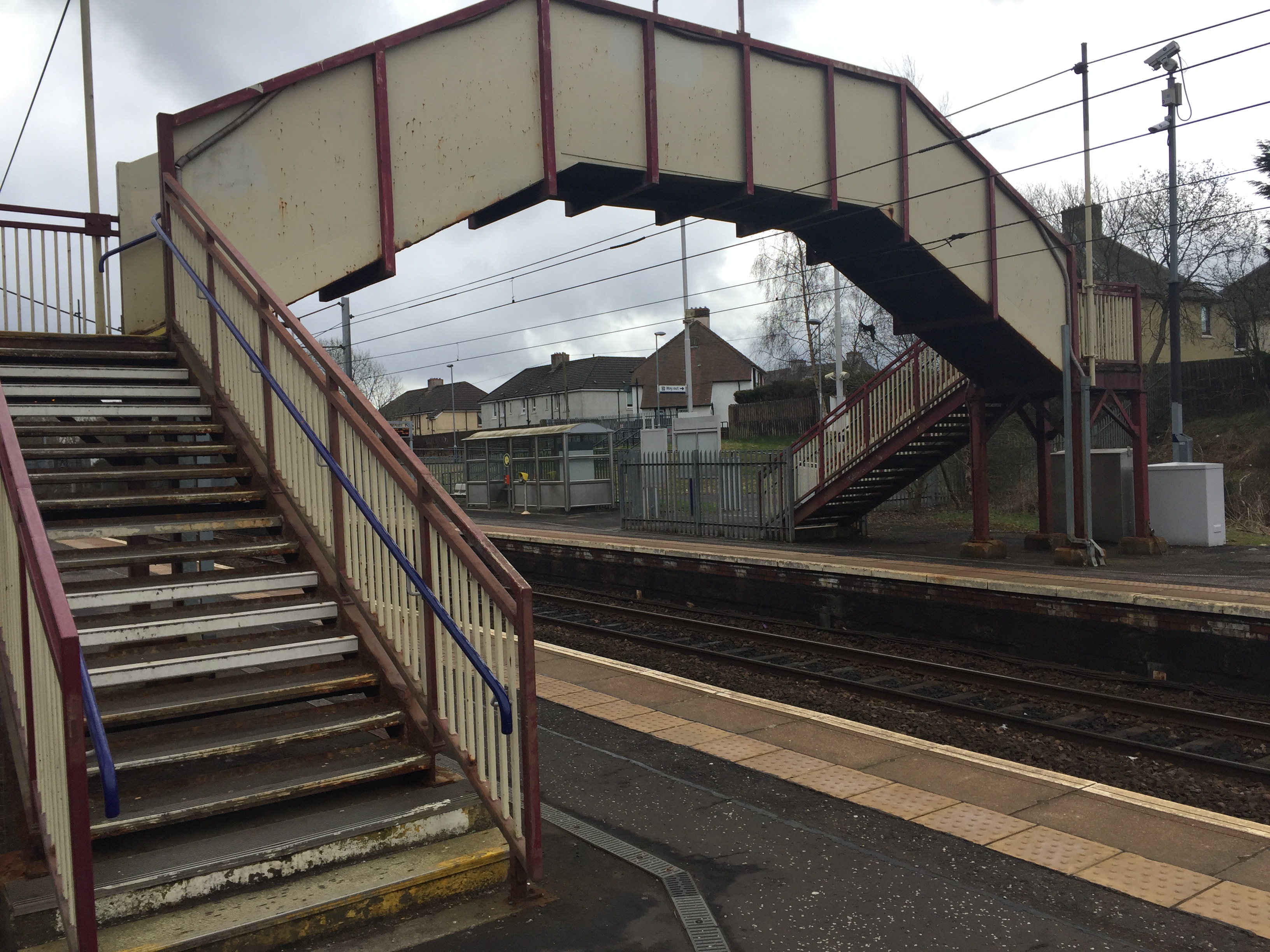
Levels were taken on inside running line of rail track, platform edge, platform extents footpath edges and centres. On roads, top and bottom of kerb lines were taken along with road centre to ascertain camber. Building footprints were observed with levels taken either side of door openings. Soffit and cill levels were taken by reflectorless measurement on buildings and underside of bridges. Stairs were taken at front edge of each riser with levels on centre of walkways and landings. Ample points were observed to show the position and orientation of all service covers and street furniture. On completion of each set up observations were made back to the reference object to ensure that no drift greater than ± 0.1m in 100.00m had occurred within instrument position.
A MHB method statement for topographical survey and risk assessment was carried out for all sites and a tool box talk was conducted by staff immediately before commencement on site. A COSS briefing was attended in addition for nightshift works to highlight any other activities which may be going on along the line and when to be clear of tracks.
As the survey was carried out to the specifications detailed in Network Rail document NR/L3/TRK/3101 Topographic, engineering, land and measured building surveying guidelines the 3D CAD drawing is compliant to BIM level 3.